Be it with a test circuit, or a simulator, test everything. Some things are so glaringly obvious that you don’t need to, but when it comes to power electronics, I cannot overstate the need for reading the data sheets.
MOSFETs (Metal Oxise Semiconductor Field Effect Transistors – try saying that after a few drinks) are great, but they have needs. And like any attentive partner, you need to take care of them, or they will blow up in your face. They like to be driven hard, with quite a lot of current, but not too hard, or they will pop.
Spice is a tool that was designed to profile the behaviour of semiconductors and it doesn’t take too long to setup a simulation of a circuit and observe a few waveforms to see if it looks right.
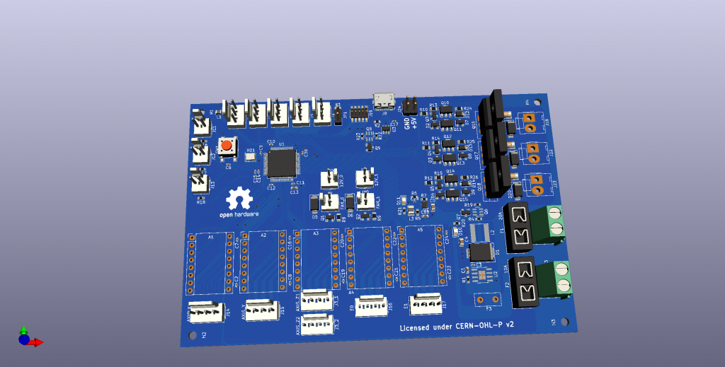
Why am I writing this? Well, my new generation RepRap board design needs to drive some high current DC outputs for heater elements. I can foresee the need for up to 20A drive, and a MOSFET will do that for me. But MOSFET’s in that size, typically have a gate voltage threshold at around 4v. I’m running my MCU at 3.3v, so I cannot simply plug that signal into the MOSFET and expect it to work.
According to the datasheet – the safe region if the switching time is <1uS, covers the full range that the device is specced for. I want to run 24 volts, ~20A of current, and a £0.85 device from RS does everything I need it to.
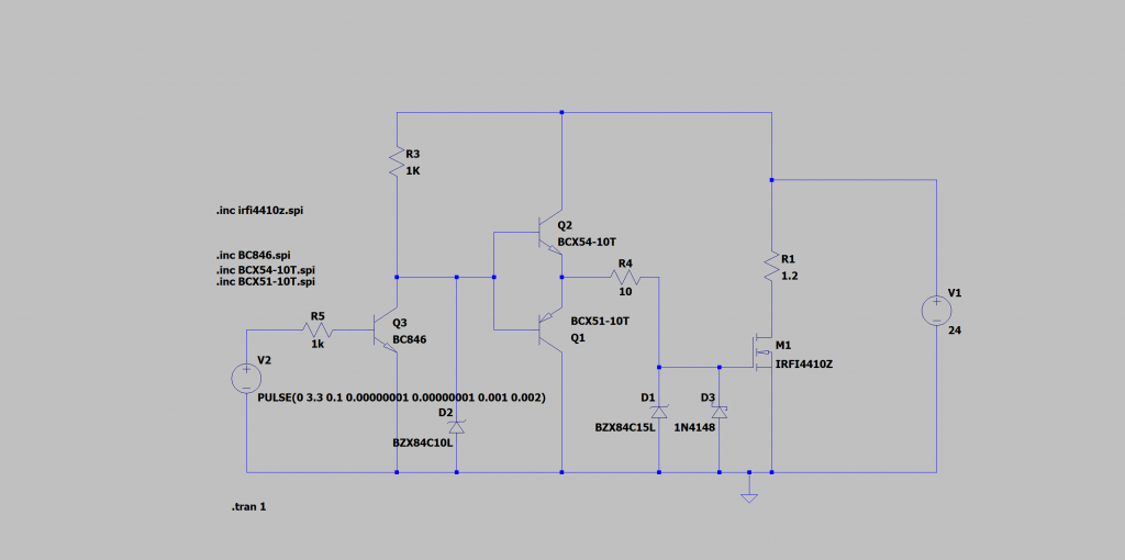
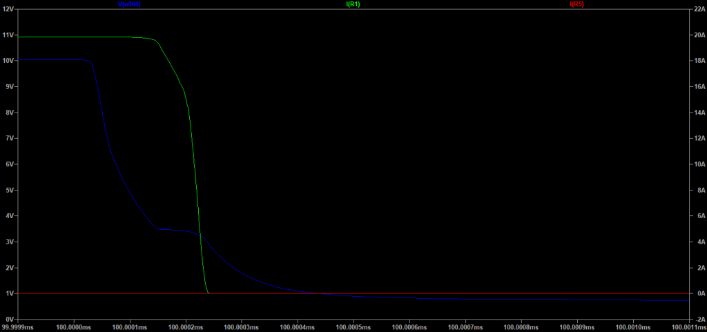
I had some challenges though – I want it to drive a 24V line (mostly resistive load) and the device cannot exceed 20V at the gate. Using a Zener to clamp the voltage at 10V solves that issue, and as the currents on the input to the follower pair in the totem pole are low, it should not be a major concern. I did explore a monolithic device with a NPN and PNP matched pair, but that was quite expensive (£0.50 for the device, vs £0.05 for both combined). Board space was quite free, so I took the low cost option. If I had a space constraint, I would definitely take the pair. I may have over sized the components – I said it needs to be driven hard, and that means a lot of current, just over half an amp goes into the gate at switch on, and the same goes back out of it at switch off – but these are transient currents, not continuous, I could probably get away with smaller rating devices, but I’d prefer to err on the side of caution. For safety, I’m including a Zener to clamp the input voltage on input to 15V (we should never see it, but it’s better to be safe than sorry), and a Schottky helps to dampen out any ringing that may occur (overkill, but worth it).
Not shown here is a flyback diode over the load that protects on inductive loads (it’s in the final design though) and I should therefore be safe to drive a relay (at appropriate speeds!) if I ever need to.
Whilst I was in LTSpice, I also profiled my smaller driver for fan control, and this was pleasantly well within specs for the device. As it only needs to switch a max of 0.5A, everything is correspondingly smaller, and the 4mA that the MCU needs to provide is well inside of of spec. At 3.3V it’s also plenty high enough without any extra components to fully drive it, but it’s a full 4uS to full open (but well inside of the specification!)
I’ve had to adjust my board design a little bit, but now I’ve got much higher confidence.
Leave a Reply
You must be logged in to post a comment.